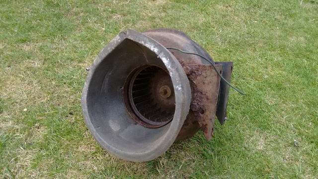
Although the actual blower was working I wanted to remove it to clean off any rust from the case and to inspect the bulkhead area behind it (see previous). As expected, the thin ‘snail’ case is extremely rusty. The resistor had become unwound although still working. I measured the resistance of this as 1.5Ω if anyone needs to replace theirs.
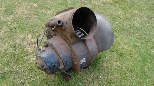
I will probably refurbish this unit during the winter months (a nice ‘shed’ project for a wet Sunday afternoon) but it will probably go on Ebay to help fund other jobs. Although some say the heating system is adequate providing it’s in good condition, I have never found a series Land Rover to be warm enough in winter. Maybe I’m soft but I would like to improve it if I can.
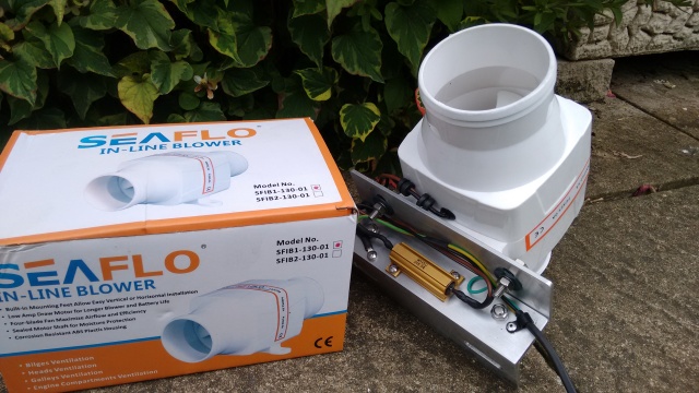
I have decided to use a marine ‘bilge blower’ unit in place of this lump and bought one from Ebay for £14.69 including postage. I chose a 3″ unit over the 4″ option so I could use the normal duct between it and the radiator unit. This ‘SeaFlo’ unit is supposed to shift 130cfm, I find it difficult to visualise the volume of air shifted so it’s a bit of a guess as to whether it will work.
Resistor for dual speed operation
I guessed that 9v would be a good starting point for the low speed setting and worked out that to drop around 3 volts would require a 1.5Ω resistor (which turned out to be the same value as the wirewound resistor mounted to the old blower), and rated at 7w. So I bought a metal-cased, chassis-mount ceramic resistor rated at 50w.
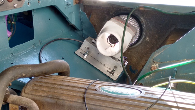
Mounting bracket
I scrounged a bit of heavy aluminium angle from my good friend Trevor and made a mounting bracket for the fan and resistor and made the soldered connections, insulating them with heat shrink tube. I encased the flying cables within a length of heat-shrink and fitted rubber grommets to the exit holes and a cable grip. To add in copious adjustment capabilities I slotted the mounting holes for the bulkhead fixing bolts and fan housing and added rubber grommets to the bolts to help deaden noise from the motor.

Calais Kerfuffle Curtails Completion?
The wing-mounted air intake has a diameter of approx 5″ so I need an adaptor to get down to the 3″ blower intake. I searched online for such a fitting but the only one I could find was in France where the local plumbing system must use these sizes.

Two weeks later it’s still stuck somewhere in France, possibly due to the delays at Calais I imagine. I won’t make a fuss as I don’t want to cause a diplomatic incident, even if it might make my blog more widely-known. So I will wait patiently and get on with other things. Meanwhile I test-fitted the unit and it looks good:

how much do you think you increased the airflow?
LikeLike
Hi, not sure how to tell scientifically but it is very much increased, maybe twice the amount of air. If the unit were to fail though I would replace it with an even more powerful one, as the older I get, the more heat I need. Thanks for your question, Nigel.
LikeLike
https://forums.lr4x4.com/topic/62485-supercharging-your-heater/
here you have a good idea too. I went this way, and I got about 1.5 times more airflow.
but still not enough for a warm defender.
LikeLike
That’s a lovely job and some interesting discussion in the comments too, maybe I’m not such a softie after all, needing the extra heat.
LikeLike
Hello,
This is fantastic and you have provided really clear instructions. I’m trying to do the same thing, but can’t seem to get the blower to work on low (running through the resistor). I’ve checked it with the multimeter and I do have voltage. I’ve also checked the wiring and made sure I had continuity. Finally, I unplugged it from the resistor and plugged the wire into the “high” wire and it worked. So I know I have voltage and continuity.
Any ideas?
Thanks in advance and thank you for this post!
LikeLike
Hi Scott, I’m glad you liked the page, sorry that I haven’t done anything worth writing up for ages. What voltage do you have on the other side of the resistor?
LikeLike
Sorry about the delayed response! It looked like about 10V. I went ahead and finished the installation but can troubleshoot more in a few weeks. I needed to get it in. I looked up the specs for the motor and it said it worked with +/- 10%.
LikeLike
I think 10v should be enough to start it. You could try shorting out the resistor and seeing if it works, this would prove your wiring. What happens if you start it at full then switch to the low setting while it’s still spinning?
LikeLike
I think I found the issue – I must have measured something wrong but the resistor is the wrong one… I got a 1.5k ohm, not 1.5 ohm…
I’m not likely to pull this out until the holidays, but that would make sense…
I’m not a sparky but it seems straight forward…
LikeLike
Well done Scott, that would explain it.
LikeLike
I only have just gotten to the resistor, as I was waiting for a job that needed taking the wing off. I put the proper resistor on and it works a charm. Thanks!
LikeLike
That’s great news Scott, well done!
LikeLike