I’ll start with a quote from a previous post: “…a couple of hours will have this looking reasonable again in my next session…”
As I’d replaced quite a few wires that terminate behind the dash it was time to tidy them so I could screw it back into place before moving on to fitting the exhaust. As an ex telephone exchange maintenance technician, the birds nest of wiring behind the dash is fairly trivial-looking but I’ve never got one sorted to the standard I’d like and this one will be no exception.
I pulled off and labelled most of the connectors so the wires could be grouped and tied, then as usual, a voice in my head told me that it would be plain silly not to have those grotty instruments out and give them a clean…

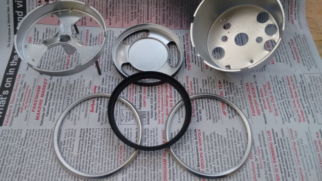
The state of the instruments wasn’t so bad, mainly cosmetic issues, with a little rust here and there, but as others have noted, the tarry substance used to seal the glass to the gauges had melted, seeped out and dried to a hard black crust around the edges.


Inspired by shamelessly copying Ian’s idea over at Mud4Fun I opted to make the gauges more visible at night by coating the inside of the housings with a more reflective colour than the blue chosen by Land Rover. So all metal parts were soaked overnight in white vinegar, cleaned up and coated with zinc primer then silver / chrome-effect paint.
LED upgrade: Warning lights and instrument illumination
Many years ago, for my lightweight (with 24v electrics) I made up my own LED lights for all the warning lights and instrument illumination by carefully dismantling each MES bulb, soldering in a resistor and an LED, then potting with epoxy resin. This was a very fiddly job but the results were pleasing. While ordering a set of rubber seals for the instruments, I noticed that the Ebay seller also supplies sets of professionally made LED bulb replacements, very reasonably priced so I ordered a set:

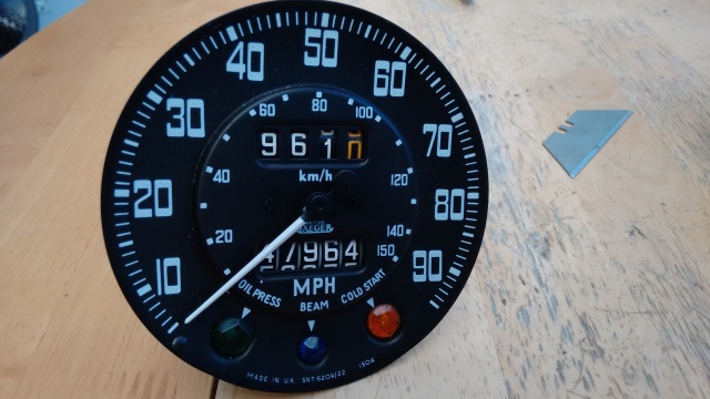
The white paint on the speedometer needle had a few cracks in it so I very carefully masked the face and sprayed it. For this operation I steady myself with a ciggy and wore my X3 Lidl’s reading glasses that make my eyes look huge, the needle is very delicate.

My time for Dilly has been so limited this year, due in part to me hopelessly underestimating a large software project for a client and spending most of my spare time at work. So I grab a half hour in the evening, after tea, sitting in the conservatory to de-stress doing these kind of jobs with a couple of roll-ups, strong tea and the radio before getting back to work. This normally coincides with The Archers which has literally caused me nightmares of late (#FreeHelen). It was silly to do such a delicate job as the evil Rob Titchener trauma nears its climax in my left ear but I somehow managed to not bend the needle.
Fitting the bezels, beware of my big mistake!
I was reasonably happy with the chrome-effect paint on the bezels, they’d been in the airing cupboard for a few days and the paint seemed reasonably hard so I got together the seals, the cleaned up glasses and started re-assembling the gauges.
I did the Fuel/Temp/Charge instrument cluster first, I carefully bent the tabs on the bezel to a loose-fit angle, located it, twisted it into position, then whilst squeezing the assembly tightly by hand, bent the securing tabs fully home. It looked great, very smart, so on to the speedo.
Whatever I tried, the bezel wouldn’t locate, it was way too tight, it seemed that the seal was too thick, and the glass just didn’t seem to sit properly in the housing. After lots of bad language I noticed that the chrome-effect paint hadn’t in fact hardened and was now a mass of fingerprints and had become more a ‘mottled grey-custard-skin-effect’, so I put it away until the next day, safer than launching it up the garden I thought. I’m sorry that you won’t be seeing the damaged paintwork photo, it would be too comical for a serious blog such as this.
Next evening it dawned on me, the speedo glass must be very slightly smaller than in the other instrument. Dissembling the latter confirmed this, there is about 1mm difference in diameter.
By now the tabs on the bezel were weakened and they would need stripping and respraying so I decided to get replacements. I was annoyed as I’d seen these for sale at silly prices, plus just-as-silly delivery charges, but I found that Auto Electrical Spares of Warwickshire do them for a more reasonable £7.49 each so I ordered a pair along with some electrical items.
I am very pleased with them. They are slightly thicker than the originals. They do them in black (as original) or plain brass, but I opted for chrome. Having the correct glass in them made assembly a five minute job.

The plastic panel had a few cracks so I repaired these with superglue and for strength glued plastic on the underside that I fashioned from an empty wash-capsule container. The test / aux / map-light jacks are very close together, the positive terminal is not even fused* and they are insulated by a thick piece of cardboard that had just about deteriorated. So I replaced this with a small piece of plastic angle.
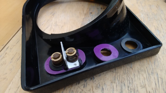
I then sprayed the front with ‘Back To Black’** and it polished up nicely.
* I will modify this wiring so this connection is fed from the spare fuse position.
** You shouldn’t really use this stuff near electrical items due to possible silicone contamination but I think if the switches have made it this far they will survive. I remember from my BT days the millions of pounds worth of irreversible damage that was done within telephone exchanges before they discovered the effects of silicone contamination caused by cleaning products.
I will add a post in a day or so, all being well, to show how it all looks once back in the vehicle, thanks for reading!

Brilliant work Nige – now my S-Max is coming up to 50K miles and could do with a bit of attention hmmm hmmm
LikeLike
Thanks Mog, please take my advice and don’t start, more music projects please 🙂
LikeLike
Great blog – boy I feel very inferior reading about your attention to detail.
LikeLiked by 1 person
Don’t feel inferior Trev, it’s an illness!
LikeLike
Great work, and I really enjoy reading your blog. What tool do you use to loosen the nuts on the back of the auxiliary sockets? I’m struggling with mine. Thanks
LikeLike
Thanks! I do have a set of ‘ring driver’s which are a hollow tube with two spikes at the end, mine have wooden handles and we used them at BT for use on ‘Strowger’ switches – a ‘retirement gift’ 😉 But as I was unable to locate the one that fits (not seen since moving house) I was able to undo them with sturdy long-nosed pliers inserted in the slots. I know they get very stiff so you might need some easing oil first, also very expensive to replace if broken so good luck.
LikeLike
Great work as usual. Wow those chrome bezels look gorgeous. I may treat myself to some. 🙂
LikeLike
Thanks Ian, yes those bezels are nicely made and I’m looking forward to fitting it all back in the vehicle, unfortunately I won’t be getting a weekend this week though. I’m still trying to work out which LED goes where, also how and if the charge lamp affects the exciter circuit, it may be best to leave a conventional bulb in that one.
LikeLike
Another great post with lots of great knowledge!
Thanks!
LikeLike
Thanks for your support!
LikeLike